Modules can either be defined manually, they can be discovered "de novo" from sequence data (either DNA tracks or motif tracks) by module discovery programs, or they can be derived based on interaction partner annotations in motifs. Once a collection of modules has been defined, the moduleScanning operation can be employed to search for instances of these modules in either motif tracks or DNA tracks (depending on the particular module scanning program used). Both the moduleDiscovery and moduleScanning operations will return module tracks, which are a special kind of region track where the type property of the regions correspond to module names. The regions of a module track are nested regions where the top-level regions correspond to the full module segment and the child regions correspond to the component motifs of the module.
Module definition
The definition of a module consists of two parts:- A set of component motifs (sometimes also called module motifs or meta motifs)
- A set of constraints (optional)
A module represents a group of individual binding motifs which are referred to as the component motifs of the module. For example, in a module consisting of binding motifs for the interacting transcription factors SP1, NF-Y and SRF, the component motifs will of course be SP1, NF-Y and SRF. However, in MotifLab these component motifs do not correspond directly to the motif data type. Rather, component motifs represent an intermediate level of "meta-motifs" that are basically sets of equivalent binding motifs for the same TF. The reason for this is that a single TFs can be associated with multiple motif models (for example, the Heat Shock Factor has 12 different motif models in TRANSFAC Public alone!). So, if factor A is represented by N motifs and factor B has M motifs, one can simply define a single module for factors A and B rather than having to define N×M individual modules covering every possible combination of motifs for these two factors.
|
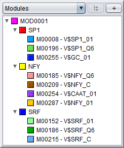
The figure on the right shows a module as it is displayed in the Motifs Panel. The structure of the module is visualized in a three-level hierarchy. The top-level is the module itself, named MOD0001
The second level is made up of 3 component motifs, named respectively SP1, NFY and SRF, and the third level lists the basic motif models associated with each of the component motifs (three models for SP1 and SRF and four models for NFY).
Note that the colors used for the component motifs need not correspond to the colors for the individual motif models at the level below.
Even thought the definition of the module allows its component motifs to be represented by multiple motif models, a specific module region (the occurrence of module site within a region track) will only have one motif model corresponding to each component motif site. For example, the module MOD0001 could be made up from TFBS corresponding to the motifs M00008 (SP1), M00209 (NF-Y) and M00152 (SRF) at one module site, but be made up of TFBS sites for M00255 (SP1), M00185 (NF-Y) and M00152 (SRF) in a different location. Since it is common for different motifs representing the same TF to have overlapping sites in a motif track, it would also be natural for the same module to have multiple overlapping sites representing different combinations of the underlying motif models. For example, if the MOD0001:SP1-NFY-SRF module existed at a particular location in the sequence and all of the underlying motif models matched their respective TF sites (3 models for SP1 and SRF and 4 for NF-Y), a straight-forward module scanning method could potentially predict 3x4x3=36 overlapping module sites for the same MOD0001 module at this location to cover all possible motif combinations. Note that it is also technically permissible for a module site to lack some of the component motifs. |
 |
Module constraints
In addition to the component motifs, the module can also be fitted with optional constraints. These constraints can either be global (applying to the module as a whole) or local (applying to a single component motif or the space between two component motifs).
-
Global constraints:
- Max span: The maximum width of the whole module. All the component motifs of the module must be located within a sequence window of this size
- Ordered: In an ordered module, the component motifs must appear in a specified order, whereas in an unordered module they can appear in any order. If the module is ordered, additional constraints can be placed on the distances between pairs of component motifs
-
Local constraints:
- Motif orientation: It can be specified that a component motif must have a certain orientation (direct or reverse) relative to other component motifs. Note that since this is relative, at least two motifs must have this constraint in order for this to make sense
- Distance between motifs: In an ordered module, it is possible to place constraints on the distance between two consecutive motifs. This could be a minimum distance, a maximum distance or both. Distances can also be negative (i.e. allowing overlap)
Module properties
A list of standard module properties are described below. In addition to these, modules can also have extra user-defined properties.| Property | Description |
|---|---|
| ID | The ID or identifier of a module is the same as the name of the module data object. This is set when the data object is created and can not be changed later. The ID is usually in the form of an incremental identifier (e.g. MOD1043), but it could also be a more descriptive name (as long as it adheres to the naming rules for data objects) |
| Component motifs | The "meta-motifs" (motif equivalence sets) that represent binding motifs for each individual binding factor in the module |
| Cardinality | The number of component motifs in the module (this is a derived property). |
| Max length | Also called "max width" or "max span". An optional global constraint specifying the maximum number of sequence bases that the module is allowed to span |
| Ordered | An optional global constraint specifying whether or not the component motifs must appear in a specific order within the DNA sequence |
| GO | A set of gene ontology terms that describe the module |
Creating a module in the GUI
You can create a new module by selecting "Add New ⇒ Module" from the "Data" menu or alternatively pressing the "+" button in the Motifs Panel and selecting "Module" from the drop-down menu. Note that the modules you create will only be displayed in the Motifs Panel if the drop-down box above the panel is set to "Modules". Or if the modules are part of collections or partitions you can also see them by selecting these two options.1) Specifying the component motifs
In the Module dialog, press the "Add motif" button to add a new component motif to the module. New motifs will be added to the end (right-hand side) of the module. By default, the module will be ordered, which is indicated with angular connector lines between the component motifs. If you uncheck the "Motifs must appear in order" box, the module will be unordered and the connector lines will not be displayed. It is currently not possible to rearrange the order of the component motifs within a module. You can remove a component motif by selecting it and pressing the "remove button". To select a component motif, simply point at the motif box (or above or below it) so that the box border changes to a red color, and then click. The selected portion of the module will be highlighted with a blue background, and all the settings that apply to this component of the module will be enabled in the dialog (such as name, select motifs, color and orientation).
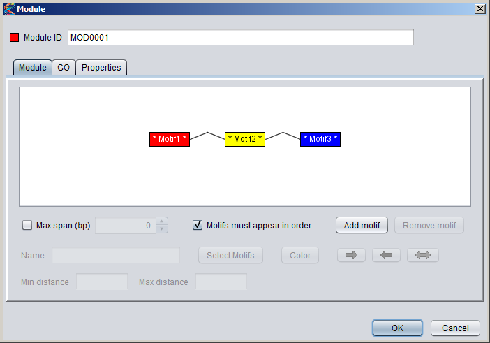
Newly added component motifs will be given generic names on the form "MotifN", and the name will be flanked by stars in the motif box to indicate that the motif has not been associated with any actual motif models yet (e.g. * Motif1 * ). You can change the name of a component motif in the "Name" text field of the dialog and also change the color by clicking the "Color" button.
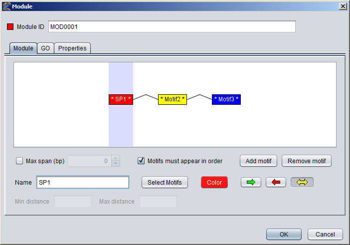
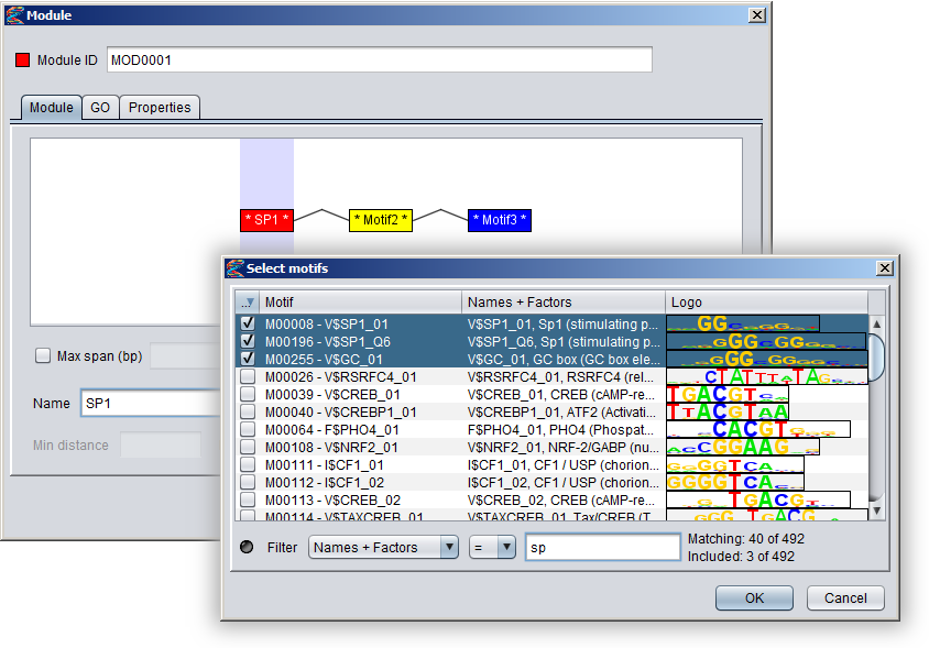
To associate a component motif with actual motif models, either select a component motif and press the "Select motifs" button or double-click on the component motif in the visualization. This will bring up a motif browser where you can select which motifs models to use. Once a component motif has been assigned at least one model, the stars flanking the name in the motif box will disappear. You can hover the mouse over a motif box to see which motif models have been selected for that component. Note that all component motifs must have been assigned at least one basic motif, or else you will not be able to press the "OK" button to close the dialog and create the module.
2) Setting distance constraints
You can specify a global max length for the module by checking the "Max span (bp)" box and then setting a number in the adjecent field. This constraint is taken to mean that all the component motifs of the module should be located within a sequence window of this size.
If the module is ordered you can also specify distance constraints between adjecent pairs of component motifs. To specify such a constraint, simply point to a connector line between motif boxes (the line should turn red), and click to select it. The selected connector should then be highlighted with a blue background, and the settings that apply to this connector will be enabled in the dialog. When you enter numbers into the min distance and max distance fields, these values will appear in brackets above the connector line. It is possible to leave one of the limits blank (either min or max) to say the the distance should be unconstrained in that direction. This will be marked with an asterisk in the brackets, as can be seen for the connector between the NFY and SRF motifs in the figure below. If both limits are left blank, the constraint will be removed.
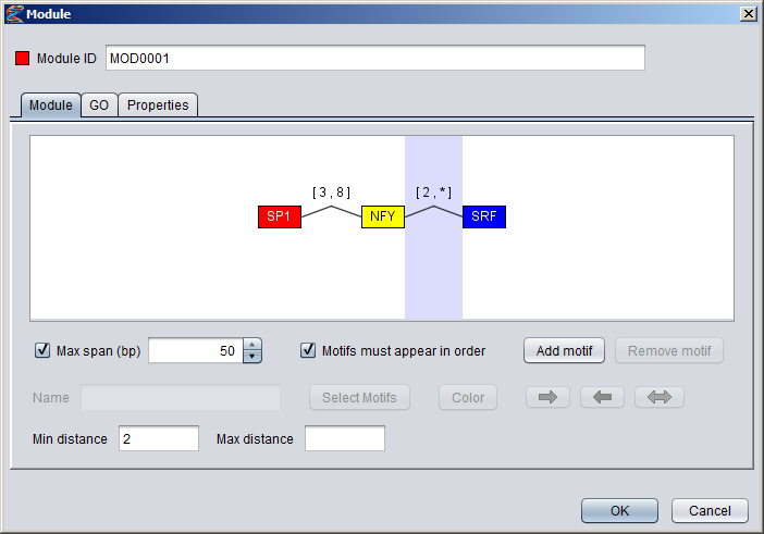
3) Setting orientation constraints
It is possible to declare that the component motifs should occur in specific orientations relative to each other. To set an orientation constraint on a component motif, first select it in the visualization and then click on one of the colored arrow buttons underneath the "Add motif" button. If you select the "Direct orientation" button, a green right arrow will also be displayed above the component motif box in the visualization (see motif SP1 in the figure below), and if you select the "Reverse orientation" a red left arrow will be displayed above the motif box (motif SRF in the figure). If you select the yellow "any orientation" bidirectional arrow, the orientation constraint will be removed from the motif and no arrows will be displayed above the motif box (motif NFY in the figure).
Note that a direct orientation constraint does not imply that the motif has to be located on the direct strand (and likewise for reverse orientation). It simply means that the underlying motif model must match the DNA sequence in its default (not reverse) orientation, but this could potentially occur on either strand of the DNA sequence. Since orientation constraints are relative, they only make sense if at least two of the component motifs have such constraints.

Creating a module in a protocol
A new module can be created in a protocol script with the following general syntax:
MOD0001 = new Module(... list of property arguments ... )
The arguments are specified as a semicolon-separated list of property definitions, where the name of the property is case-sensitive. The first property argument must be CARDINALITY and its value must match the number of MOTIF arguments. The standard property arguments are described in the table below. Properties that are not in this table are considered to be user-defined properties and must be specified as "propertyname:value" pairs.
| Property | Description |
|---|---|
| CARDINALITY | This defines the number of component motifs in the module on the format: CARDINALITY:<n> This must be the first argument! |
| MOTIF | Defines a component motif of the module on the format: MOTIF(<name>)[(<orientation>]{<list of motifs>} The "MOTIF" prefix is followed directly by a name for the component motif in parentheses. This is then followed by the orientation of the component motif in brackets. The orientation can either be "+" (direct orientation), "-" (reverse orientation) or "." (for unordered motifs). Finally, the basic motifs that make up this component motif is listed (comma-separated) within a pair of curly braces. For example, a direct-oriented component motif for the SRF transcription factor based on the three TRANSFAC models M00215, M00152 and M00186 can be defined as: MOTIF(SRF)[+]{M00215,M00152,M00186} Note that the "MOTIF" argument can be repeated several times, and the number of times it is used must match the CARDINALITY of the module. |
| ORDERED | Specifies that the component motifs of the module should be ordered. The order is based on the "MOTIF" arguments. |
| UNORDERED | Specifies that the component motifs of the module should be unordered. This is the default unless ORDERED is specified. |
| MAXLENGTH | Defines an optional maximum span for the module on the format: MAXLENGTH:<number of bases> |
| DISTANCE | Defines a distance constraint between two (consecutive) component motifs on the format: DISTANCE:(<motif1>,<motif2>,<min distance>,<max distance>) This only makes sense if the module is ORDERED. The minimum distance can be negative to allow overlapping motifs. If you only want to constrain one of the limits in the range (either min or max) you can set the other limit to UNLIMITED or *. This argument can be repeated several times to define distance constraints between different pairs of motifs. For example, if you want the distance between the two component motifs "SRF" and "NFY" to be at least 5bp, you can specify the constraint: DISTANCE(SRF,NFY,5,*) |
| GO-TERMS | Defines a set of GO-terms to be associated with the module on the format: GO-TERMS:<comma-separated list of terms> The GO terms are numbers that can optionally be prefixed by "GO:" (case-insensitive). The numbers do not have to be padded with zeros. The strings "GO:000290" and "290" will thus refer to the same term. |
Module tracks
A module track is a special type of region track where the regions correspond to module sites. In these tracks the type property of each region site corresponds with the name of a module. Module tracks include meta-data properties that specifically tag them as such, and they can be recognized in the Features Panel by having names stylized in both bold and italics. Also, if you point the mouse at a module track in this panel, the appearing tooltip will describe the dataset as being a "[Region Dataset, Module track]".Some operations, like moduleDiscovery and moduleScanning will always return module tracks, and if you import a region track from any source, MotifLab will first check if it could potentially be a module track and mark it as such if at least half of the first ten regions correspond to known modules. You can also try to manually convert a regular region track into a module track by right-clicking on a track in the Features Panel and selecting "Convert to Module Track" from the context-menu.
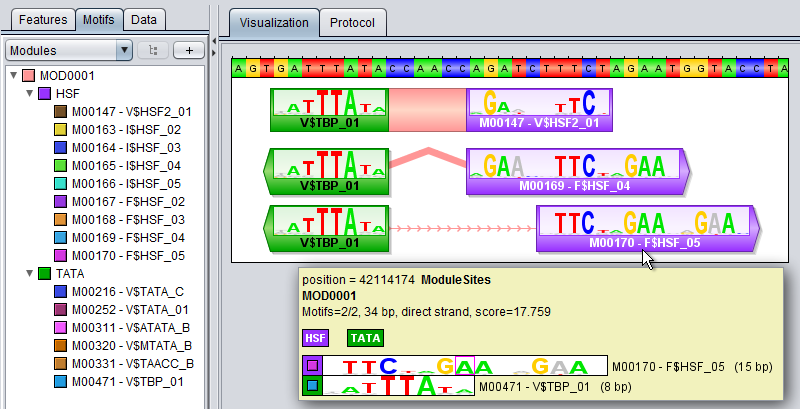
A module region or module site is a region within a module track that represents the location of a cis-regulatory module by having a type property that corresponds to the name of a known Module model. A module region is most often also a nested region where the child regions correspond to the individual TF binding sites that make up the module. These nested regions would then be motif regions whose type properties correspond to names of known Motif models. For example, in the figure below, a module model named MOD0001 is composed of two component motifs – HSF and TATA – with 9 and 6 associated motif models respectively. The particular module site corresponding to this module shown at the top of the track on the right would have the value "MOD0001" for its type-property and two additional properties called "HSF" and "TATA" that would point to two nested motif regions corresponding to the "M00471-V$TBP_01" and "M00147-V$HSF2_01" motif models respectively. (Note, however, that it is technically allowed for a module site to be missing some or all of the component motifs defined in the module).
Like motif tracks, module tracks are given special treatment by the GUI's track visualizer, both with respect to how the module regions themselves are drawn and also how their tooltips are rendered when you point the mouse at a module region.
In MotifLab version 1.x, the regions of module tracks (and also other nested tracks) would be drawn in two steps. First, a box would be drawn to represent the full module region, and this would be colored according to the chosen color for the module (at least if the "color by type" option was enabled for the track; if not, the module box would be drawn in the selected track color). Second, the individual TFBS of the module (the nested regions) would be drawn on top of this background box in their respective motif colors. An example of this style is shown for the top-most region in the figure above, where the module site spans the full 23bp sequence segment GATTTATAccaaccAGATCTTTCT. The left-hand side of the module site is made up of a TFBS for the TBP factor (green) and the right-hand side is a site for the HSF factor (violet). The middle part "CCAACC" is just inter-motif background sequence where the color of the module itself shines through in pink. The visibility of all module sites corresponding to the same module could be toggled by clicking the colored box in front of the module in the Motifs Panel, and it was also possible to toggle the visibility of the constituent TFBS sites independently of the module by changing the visibility of the motifs.
Version 2.0 of MotifLab introduced more ways to visualize modules with different styles of connectors between the component motifs. In addition to the normal background box, modules can now be visualized with straight line segments connecting adjecent motifs, or with angled lines (see second module site in figure above), with curves or with "ribbons". The connector style can be selected by right-clicking on a module track (or other nested track) in the Features Panel and selecting the connector from the context menu. Alternatively, you can select a track (or multiple tracks) in the Features Panel and press the "L" key to cycle through the different connectors. If the "visualize strand (orientation)" option is enabled for a track, the angled line, curved line and ribbon connectors will be drawn pointing upwards if the orientation of the modules correspond with the orientation that the underlying sequence is currently visualized in (i.e. the module is "oriented towards the right-hand side of the screen"). If they have the opposite orientation (module is oriented "towards the left"), the connectors will be drawn pointing downwards.
The visualization of module sites and their tooltips will differ somewhat depending on whether the module track is visualized in contracted mode or expanded mode, and the differences between these two modes are described below. You can switch between these modes by selecting a region track in the Features Panel and pressing the X or E keys, or by right-clicking on a track and selecting the mode from the context menu.
Expanded Mode
In expanded mode, overlapping module sites will be drawn beneath each other so that every region is clearly separated from the other regions and distinctly visible in the track.
- The "visualize score" option has no effect in this mode. All modules and TFBS sites are drawn with the same height.
- If the "visualize strand (orientation)" option is enabled:
- The boxes of the modules' constituent TFBS sites will be drawn with protrusions indicating their orientation (but only in zoom levels 1000% and above)
- If the straight line connector style is chosen, the connector lines will be decorated with small arrows indicating the orientation of the module itself
- The position that the mouse currently points to within the sequence followed by the name of the track (in boldface)
- The name of the module that the mouse is pointing to
- The third line contains additional information about this particular module site:
- The cardinality of the module model (after the slash) preceeded by the number of TFBS sites that actually appear within this particular module region (before the slash)
- The sequence span (length) of the full module site (in bp)
- The orientation of the module site (not the orientation of its constituent TFBS sites)
- The score of the module site
- The fourth line shows a visual representation of the module model. If the module is ordered, the boxes representing the component motifs will be drawn with angled connector lines. If a pair of adjacent motifs has an associated distance constraint, this will be indicated with a pair of brackets above the connector.
- The last part of the tooltip contains information about each constituent motif of the module (as shown in the visualization on the line above), with each box there corresponding to one TFBS line (in the same order). Each TFBS line starts with a pair of nested colored boxes. The outer box has the color of the component motif and the inner box has the color of the actual motif that represents this component at this particular module site. This is followed by the motif match logo for this motif and then the name and size of the motif. Similarly to motif tracks, if the mouse pointer points to a base position within a TFBS, that position will be hightlighted with a pink rectangle in the corresponding motif logo. For example, in the figure above, the mouse points to the middle "A" in the TFBS site for the HSF factor, so this position is indicated with a rectangle around the "A" in the corresponding motif logo shown in the tooltip.
Contracted Mode
In contracted mode, all the regions are visualized on the same line and overlapping regions will thus be drawn on top of each other.
- When the "visualize score" option is enabled, the height of the constituent TFBS sites within the modules will be scaled according to their scores. However, the module regions themselves will always be drawn at full scale.
- If the "visualize strand (orientation)" option is enabled the track will be divided into two vertical halves by a middle line:
- The boxes of the modules' constituent TFBS sites will be drawn above the middle line if their orientations correspond with the orientation that the underlying sequence is currently visualized in. If they have the opposite orientation they will be drawn below the middle line. The boxes of the modules regions themselves will always be drawn at full height.
- Connector lines will be drawn in the middle so that their end points align with the middle divider line. Also, if the orientation of the module region corresponds with the orientation that the underlying sequence is currently visualized in, the angled, curved and ribbon connectors will be drawn upwards, or else they will be drawn downwards. However, if strand orientation is not visualized, the connector lines will always be drawn upwards from the bottom of the track.
- The position that the mouse currently points to within the sequence followed by the name of the track (in boldface)
- If all the module sites have the same module type, a visual representation of the module is included on the second line (see above). If the sites are heterogeneous, this is skipped
- The final part of the tooltip contains information about each of the overlapping module sites, with one line per site with the following information:
- Each line starts with a box which is colored after the module associated with that site. If the mouse points to a position within a TFBS site for that module, the color associated with the motif for that TFBS is shown in a smaller nested box.
- The name of the module
- The cardinality of the module model (after the slash) preceeded by the number of TFBS sites that actually appear within this particular module region (before the slash)
- The sequence span (length) of the full module site (in bp)
- The orientation of the module site
- The score of the module site